All,
Here is my first draft for the design of my 4-Guitar Selector Switch with Gain. I am using OPA2134 op-amps for the audio buffering and CD4066 analog switches for the guitar selections. I am considering using a better analog switch to reduce THD. The design goals are described at the end of this posting.
I would be most grateful for any review/comments/suggestions you all might have. If there is a way I can improve signal purity, simplify, conserve power, whatever, I'd love to know anything I've overlooked.
Also, there are specific questions I am wondering about - if anybody has answers to these questions I'd be most grateful again.
-----------------------------------------------------------------------------------
Here are links to download my schematics, both in BMP and JPG format. JPGs are a little over 200k, BMPs are close to 400k. The schematic is in two parts: the audio path and the digital control...
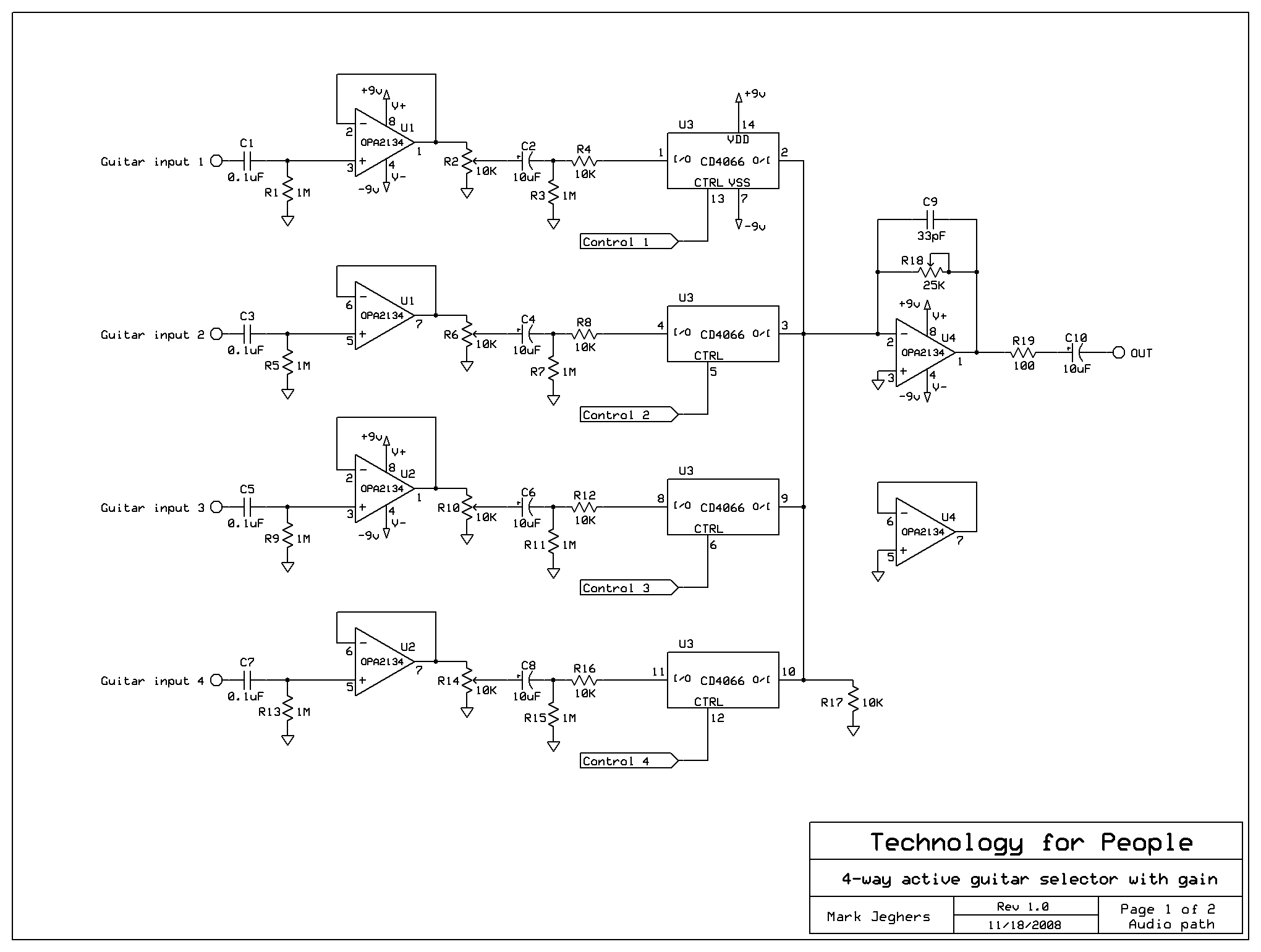
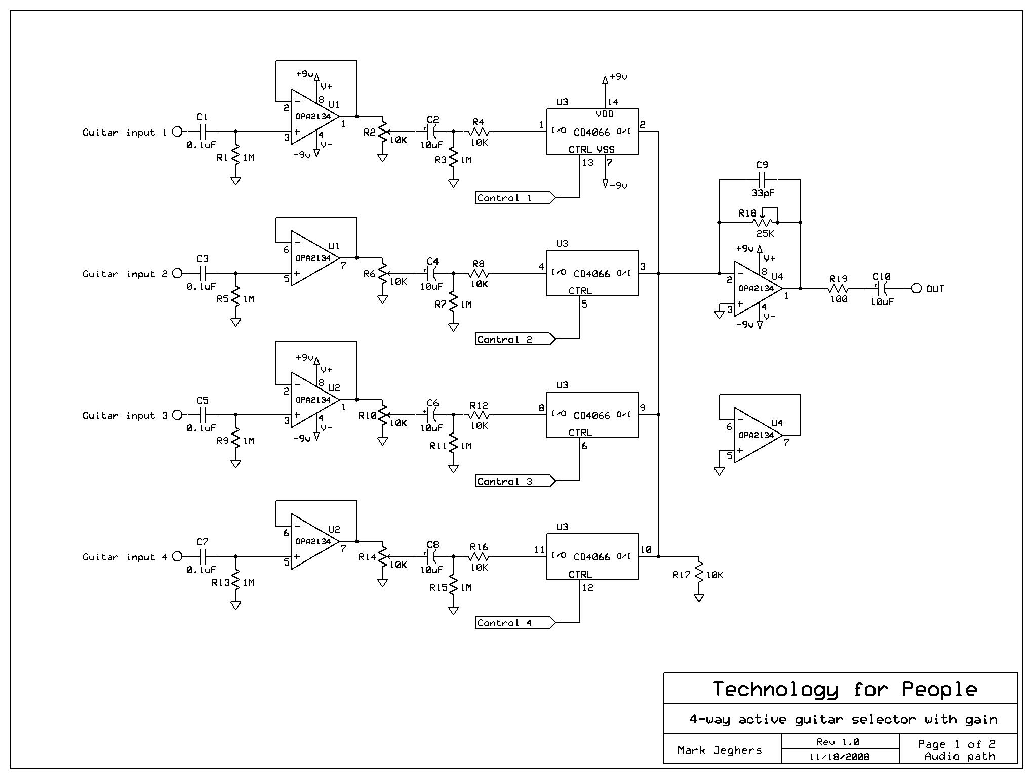
Audio Path:
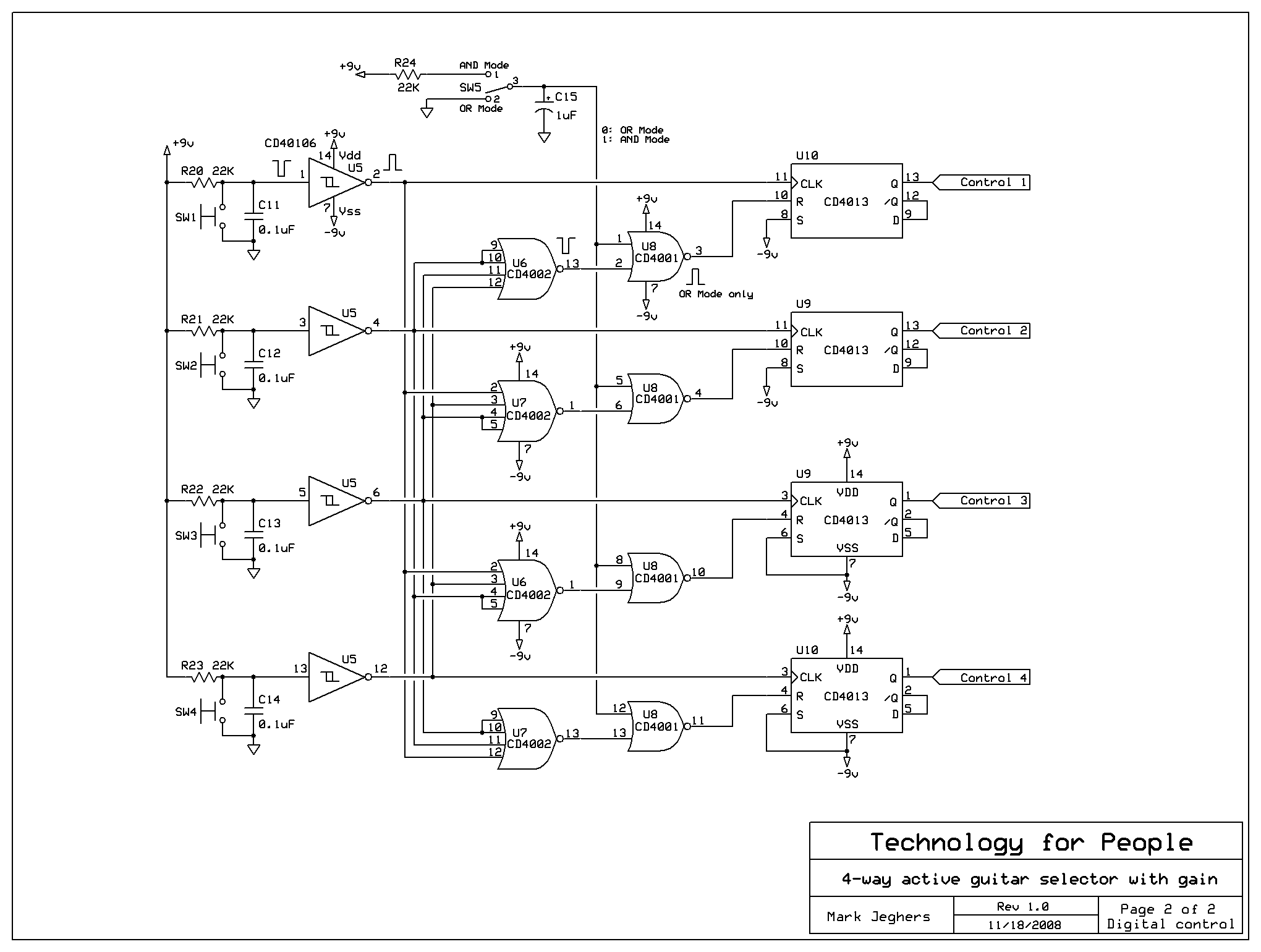
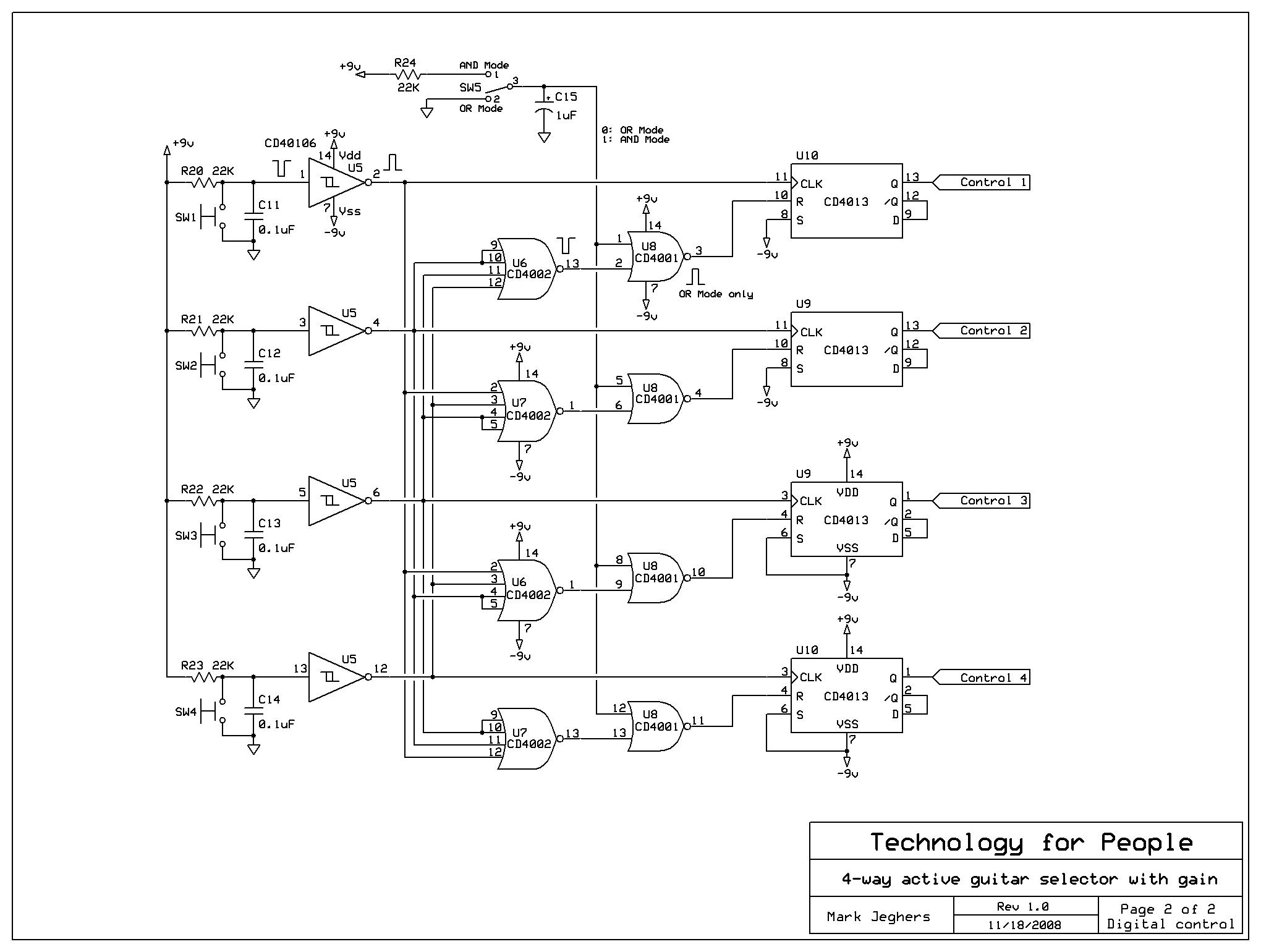
Digital Control
-----------------------------------------------------------------------------------
Here are questions I am hoping someone can help me with:
- Are my electrolytic cap polaities reasonable?
- I hear CD4066 switches still introduce some THD (enuf to negate the benefit of nicer op-amps), any other analog switches that might do better?
- Any better place in the audio path to place the analog switches? Any better way to turn the guitars on/off instead of CD4066s?
- Unity gain buffers offer hi-impedance inputs for the guitars, final op-amp mixer provides gain. Reasonable?
- Is the biasing of the op-amp inputs ok?
- Any decoupling caps that could be dispensed with? Any more needed? Are the values reasonable?
- I plan bypass caps between both power rails and ground, what values would be good?
- I plan to support both battery and extrnal power, would that affect what the bypass cap values should be?
- Would it be worthwhile to try using a single 9v power source, not bipolar (+9v/gnd/-9v)? I'd have to introduce a Vref with a power-draining resistor network, which I don't like.
- How much gain could I count on getting before the signal clips using just +9 and gnd? How much gain using bipolar (+9v/gnd/-9v)?
- Any ideas to reduce noise? To keep op-amps stable? To reduce power consumption?
- Any obvious flaws in the digital control? In OR mode, only one guitar at a time can ever be selected, in AND mode, any combination of guitars can be toggled on/off.
-----------------------------------------------------------------------------------
Here are the design goals in a nutshell:
- 4 guitars in, one low impedance output to a pedal/amp/whatever.
- Op amps allow high impedance guitar inputs so guitar tone is not adversely affected.
- The device is meant to NOT affect or "color" the tone of the guitars in any way.
- Each guitar input has a gain control (e.g. a volume knob)
- One more volume knob boosts overall gain somewhere between 3 and 12 db (I've not decided how much yet).
- Non-popping (debounced) solid-state switching with analog switches (probably CD4066s).
- Powered by either external or battery. I am willing to design for 2 9v batteries, but I'd prefer just one 9v battery if I can get away with it. Power consumption is important but not paramount.
- Digital logic (with capacitor-debounced Schmidt triggers will provide with exclusive (1-of-4) or multiple (more than one combined) guitar selection.
Thans so much in advance,
/Mark
(sorry for typos; doin this quickly while waiting for car service)
lots of questions. instead of answering all of them, I'll leave it up to you to investigate some, as that's how you will learn. quick thoughts on the analog section:
I see no power supply design. power supplies often are overlooked by new designers, and are at the root of many hum, noise and transient issues. power supplies should include regulation and filtering, and be designed in consideration with the power up/down switching ensure muting of audio circuits to avoid nasty pops. so it's not simply about "connect a battery and go." a linear regulator goes a long way toward providing supply line noise immunity -- from outside noise and RFI, as well as from internal switching transients produced in the digital control circuitry. additional filtering for regulator (when you add it) stability and also local to each opamp stage is a good idea. consider everything to be dual rail supplydesign that is ground referenced. by that, I mean filter and regulate negative supplies as well as positive.
you ask about bias. you don't really have any biasing on the '134 op amps as designed, only a ground referencing resistor (technically "biasing," but ...). that is fine for a +/- rail supply, but would not work for a single-ended supply (the single 9V battery you ask about). for a single-ended supply design, you would need to set the input DC biase level to be about 0.5*supply/voltage gain (voltage gain is a minimum of 2 for a non-inverting opamp design). I still recommend going with the +/- supply rails, as it greatly simplifies input biasing. but then, the ground referencing 1 Mohm resistor at the input brings up another issue: have you checked the input offset current specs for the '134 to understand how these will be converted to offset voltages as they are sourced through the 1 Meg resistor? might need to reduce that resistor to 500 k if these leakage/offset currents are more than a 1uA (consider: 1 uA offset current * 1 Mohm = 1 volt input offset).
electrolytic cap polarity notes: in a single supply rail (assuming positive supply), the opamp output will need to be biased to about 0.5*supply and so the caps will be biased correctly as shown. in a dual rail, ground ref system (the one I recommend), the offset voltage at the output of the first opamp thru the (trim)pot will be unpredictable -- either slighly positive or slightly negative. you can ensure that is slightly positive by pulling the input voltage slightly positive. that will require a different, more complex bias network than shown. look up biasing networks for opamps. there are several ways to do this. some also include filtering caps to keep supply noise out of the opamp input -- that usually requires 2 or 3 resistors and 1 or 2 caps. if you want to remove all electrolytic cap polarity issues and simplify, know that you can create a non-polarized electrolytic by connecting two of these caps in series pos-to-pos or neg-to-neg. either works. the effective cap value => 0.5 the original assuming you use equal value caps.
I do not see any RF filtering or bypassing in supply circuits or bias circuits. given the wide BW of the '134, you also should low pass filter the inputs and output to avoid RF and interference pickup and amplification.
can't comment on the CD4066 other than to say I seem to recall it's been around forever, and probably is not the best. I did not review the digital switching logic, but see what I say above about muting the audio during power up/down.
all this in more complicated than one initially suspects ...
-=tension & release=-
As usual, gnease has it covered.
A couple of other points:
- put a 1K series resistor in from of each of the input op-amps. This will protect the input from over-voltage, without affecting the input impedance.
- As I recall, CD4066 is single-ended, so negative signals won't work. Otherwise, it should be fine, as the series resistance is under 1K.
- If you stay single ended, as mentioned, you'll need a solid mid-reference. You can try a simple resistor divider feeding a unity-gain op-amp, but it may be too noisy.
- The intermediate decoupling caps may not be needed, as your offsets are very small. If you decide to keep them, you'll need to provide a bias voltage on the side closest to the 4066. The best way might be a 1Meg across the switches. There may be a small amount of bleed-through, but there will be zero popping.
- Non-inverting op-amps have a minimum gain of x1, unless they are specifically not stable at unity gain.
- R17 is not needed or helpful.
- If you can afford the current drain, add some LEDs so you know which guitars are ON, and whether you have power.
- The most common cheap way to improve a bypass cap is to put smaller caps in parallel with it. So a 10uf, would have a 0.1uf and .001uf cap in parallel, which will improve the linearity and ESR.
Between us, we've doubled your parts count!
- If you stay single ended, as mentioned, you'll need a solid mid-reference. You can try a simple resistor divider feeding a unity-gain op-amp, but it may be too noisy.
<snip>
- Non-inverting op-amps have a minimum gain of x1, unless they are specifically not stable at unity gain.
thanks for the gain correction, Dan. IIRC, it's 1 + Rf/Ri for positive gain, correct? think I'm used to seeing non-inv configs with the negative input either grounded or cap-coupled to ground and zero ohm Rf => minimum of 2. but trying to recall if there is any advantage grounding the negative input, other than increased stability. don't think so
I've seen active bias, bypassed tee network bias (input fed thru series R to node of supply divider and cap bypassing at that tee node), simple divider -- no supply noise rejection as you point out. usually I go for a bypassed tee.
-=tension & release=-
Thanx for the feedback, here are some thoughts/comments/further questions:
I see no power supply design. power supplies often are overlooked by new designers, and are at the root of many hum, noise and transient issues. power supplies should include regulation and filtering, and be designed in consideration with the power up/down switching ensure muting of audio circuits to avoid nasty pops.
Understood, power supply is a missing item so far. I'm hoping one of those 3-pin single-chip regulators will suffice as opposed to more op-amps. The existing schematics need a power supply section added. What special steps might minimize power up/down pops?
...additional filtering for regulator (when you add it) stability and also local to each opamp stage is a good idea.
I take for granted that the power supply would be filtered before the voltage regulators, and I am guessing small caps after the regulators might be good too, yes? Also small caps across the power pins right on each IC chip, yes?
...only a ground referencing resistor ... that is fine for a +/- rail supply, but would not work for a single-ended supply (the single 9V battery you ask about). for a single-ended supply design, you would need to set the input DC biase level to be about 0.5*supply/voltage gain (voltage gain is a minimum of 2 for a non-inverting opamp design). I still recommend going with the +/- supply rails, as it greatly simplifies input biasing.
I am strongly leaning towards a +/- power supply, not a single 9v source. In that case, biasing thru one resistor to gnd should suffice, shouldn't it? By the way, I plan to have a pair of 9v batteries as an alternative power option to the external source.
...the ground referencing 1 Mohm resistor at the input brings up another issue: have you checked the input offset current specs for the '134 to understand how these will be converted to offset voltages as they are sourced through the 1 Meg resistor? might need to reduce that resistor to 500 k if these leakage/offset currents are more than a 1uA (consider: 1 uA offset current * 1 Mohm = 1 volt input offset).
Haven't run the numbers yet, but the input current spec should be very low. But I'll check it to confirm. But also remember, I really want the 1M there to keep the input impedance of the inputs high.
...you can ensure that is slightly positive by pulling the input voltage slightly positive. that will require a different, more complex bias network than shown. look up biasing networks for opamps...
Would this involve a series resistor-divider network to tap a voltage drop off of it? That would introduce a further current drain on the power supply I would rather avoid (in case of running off batteries). Sounds like back-to-back electrolytics might be preferable?
By the way, I suppose there is nothing magical about the 10uF values -- do you think I might get away with smaller cap values there?
I do not see any RF filtering or bypassing in supply circuits or bias circuits. given the wide BW of the '134, you also should low pass filter the inputs and output to avoid RF and interference pickup and amplification.
Would that just be an RC added before the first op-amp inputs? Seems like that would affect my high input impedance goal, wouldn't it? Or is there a different way to do it?
can't comment on the CD4066 other than to say ... probably is not the best.
I am considering other analog switches with much better specs
/Mark
Laz, thanx for the feedback, here are some thoughts and questions...
- As I recall, CD4066 is single-ended, so negative signals won't work...
But I am planning to power the logic chips with the +/- power rails, so from the analog switch's
point of view, there would never be a negative signal, would there?
- If you stay single ended, as mentioned, you'll need a solid mid-reference. You can try a
simple resistor divider feeding a unity-gain op-amp, but it may be too noisy.
I really don't like the power drain of the resistor-divider approach, nor the design problems of
lower supply voltage, so I am leaning towards a +/- supply.
- The intermediate decoupling caps may not be needed, as your offsets are very small. If you
decide to keep them, you'll need to provide a bias voltage on the side closest to the 4066. The
best way might be a 1Meg across the switches...
I was meaning for R3, R7, R11, R15 and R17 to provide bias voltages, have I wired/designed them
wrong?
- R17 is not needed or helpful.
I thought it would give biasing to the mixer input, no?
- If you can afford the current drain, add some LEDs so you know which guitars are ON, and
whether you have power.
That is the plan, just not in the schematic yet.
- The most common cheap way to improve a bypass cap is to put smaller caps in parallel with it.
So a 10uf, would have a 0.1uf and .001uf cap in parallel...
Cool - never heard of that. They catch higher freq junk, I suppose?
Between us, we've doubled your parts count!
Well, that might be better than a simpler circuit that doesn't work! :wink:
CD4066 is a single-sided device, as are most logic chips. However, Maxim makes a nice family of parts that may work well for you: http://www.maxim-ic.com/quick_view2.cfm/qv_pk/4912
You should be able to buy something like that from DigiKey. If you stay with the +/- supply, then most of the references and biases go away, and your noise is improved.
Only the non-inverting input of the op-amp needs a bias. The inverting (feedback) input gets it's bias from the feedback path.
Let's see the next version.
way too rambling ...
In thinking about it, my original recomendation was to use 15 to 18 VDC supply and that sort of naturally morphed into +/- 9V due to the obvious battery considerations and possibilies. there are plusses and minuses with single versus dual polarity power supplies. the trade space includes bias complexity, signal path coupling (DC or AC), complexity of supply generation/regulation, compatibility with other subsystems (mux or switching chips), overall complexity and parts count, noise immunity ... etc. design engineering is all about making those choices. there is rarely one way to do anything, and often the real need is to make an 90% (or less!) informed decision and move forward.
If you move to single-ended supply, you could make a single bias voltage reference circuit -- low impedance source at audio freqs of interest (hint: bypass caps) and distribute it to the op amp + inputs via high-value resistors. the audio bypassing at the common point is critical to prevent crosstalk.
filtering of any sort can be done at any impedance that is practical for realizable components. in this case, the first threat you likely need to consider is AM radio stations, lowest freq of about 500 kHz. the first defense is usually passive: at the op amp input a shunt cap to signal ground whose impedance works against the source (guitar plus anything added such as series Rs and Ls. as an example: a series R (or better, but somewhat impractical, a BF inductor) creates a lowpass corner point somewhat above the audio and significantly below 500kHz, say at 75 kHz -- about 10x above the highest audio, but almost 8 x below the AM band. to calc the cap value, you first need to establish a stable source impedance (guitars are all over the place depending on settings). the easiest way is to add a series R ahead of the cap. start with 100k, as that's 10x less than the 1 M input established by the bias resistor. for a corner at 75 kHz, the cap will be about 20 pF. at the highest audio freq, that cap has about -1M reactance. in parallel with the 1M op amp input, that will look like about 707 kohm @ -45 degrees. combined with the 100k resistor that will look like a 706k @ -45ish degrees to your guitar.. pretty respectable. on the other hand, that same simple circuit will reduce a 600 kHz signal into the op amp by about 9 dB. something, but not all that much. that can be increase by upping the value of the series resistor. the other, obvious place to put input filtering is in the negative feedback loop of each op amp. that has the added plus of not reducing the op amp input impedance significantly for your application. check that out.
-=tension & release=-
